


Applicable Equipment: All CAT diesel engines, generators, excavators, loaders, trucks, and industrial power systems (C7, C9, C13, C15, C18, 3406, 3500 Series, etc.)
Document Purpose: Provide complete, step-by-step guidance for maintaining, troubleshooting, repairing, and replacing CAT temperature sensors to ensure accurate readings, optimal engine performance, fuel efficiency, and component protection.
1. Overview of CAT Temperature Sensors
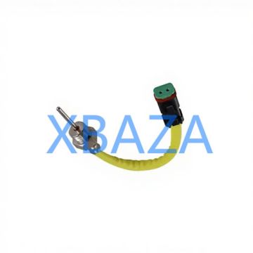
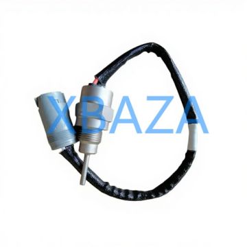
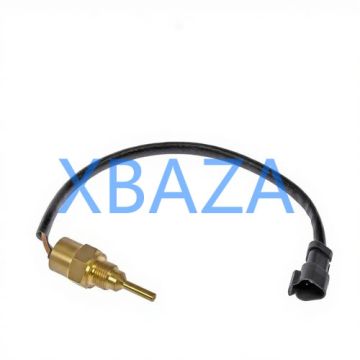
CAT temperature sensors are critical engine components that monitor real-time temperature data and send signals to the Electronic Control Module (ECM). Common types include:
- Coolant Temperature Sensor (CTS)
- Engine Oil Temperature Sensor
- Intake Air Temperature Sensor (IAT)
- Fuel Temperature Sensor
- Exhaust Temperature Sensor
Malfunctioning sensors cause rough idle, overheating, poor fuel economy, fault codes, and permanent engine damage.
2. Routine Maintenance Schedule
Follow CAT-recommended maintenance intervals to prevent premature failure:
- Visual inspection: Every 250 service hours or 3 months
- Electrical connection cleaning: Every 500 service hours
- Functional testing: Every 1000 service hours
- Full sensor replacement: Every 4000–6000 service hours (or as needed)
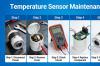
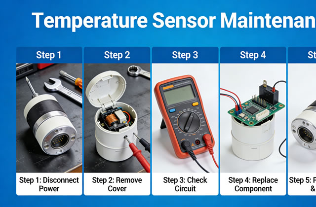
3. Step-by-Step Inspection Procedure
3.1 Visual Inspection
- Locate the temperature sensor on the engine (refer to CAT service manual for exact position).
- Check for physical damage: cracks, corrosion, bent pins, or broken housing.
- Inspect wiring harness for cuts, burns, fraying, or oil contamination.
- Check connector for water intrusion, dirt, rust, or loose terminals.
- Verify sensor mounting for leaks (coolant, oil, or fuel) and proper torque.
3.2 Electrical Connection Inspection
- Disconnect the sensor connector carefully (do not pull wires).
- Clean terminals with electrical contact cleaner and a soft brush.
- Check pin tension: terminals must hold firmly without slack.
- Apply dielectric grease to prevent corrosion and moisture.
- Reconnect securely and ensure locking clips are engaged.
3.3 Multimeter Testing (Resistance Check)
- Set multimeter to resistance (Ω) mode.
- Measure sensor resistance at room temperature (25°C/77°F).
- Compare readings with CAT standard specifications (see table below).
- Test again when engine is warm to verify linear response.
- Out-of-range readings mean sensor failure – replace immediately.
CAT Temperature Sensor Standard Resistance Values
| Temperature | Typical Resistance Range | Status |
|---|---|---|
| -20°C (-4°F) | 35,000 – 40,000 Ω | Normal |
| 25°C (77°F) | 8,000 – 10,000 Ω | Normal |
| 100°C (212°F) | 1,000 – 1,200 Ω | Normal |
| Out of Range | 0 Ω / Infinite Ω | Failed Sensor |
4. Troubleshooting Common Faults
4.1 Sensor Provides No Signal
- Cause: Broken wire, disconnected connector, short circuit, or internal sensor failure.
- Solution: Repair wiring, clean/reconnect connector, or replace sensor.
4.2 Erratic Temperature Readings
- Cause: Loose connection, corroded pins, moisture, or damaged harness.
- Solution: Clean terminals, apply dielectric grease, secure wiring.
4.3 False High Temperature Alarm
- Cause: Grounding issue, shorted wire, or faulty thermistor.
- Solution: Check ground connection, test resistance, replace sensor.
4.4 Sensor Not Communicating with ECM
- Cause: Broken data line, ECM voltage issue, or defective sensor.
- Solution: Test circuit voltage, check ECM connections, replace sensor.
5. Professional Repair & Replacement Procedure
5.1 Preparation
- Turn off engine and allow full cooling (at least 30 minutes).
- Disconnect battery negative terminal.
- Drain small amount of coolant/oil if sensor is mounted in fluid path.
- Prepare correct CAT OEM sensor, gasket, thread sealant (if required).
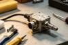
5.2 Removal of Old Sensor
- Disconnect electrical connector.
- Use proper socket wrench to loosen and remove sensor.
- Clean mounting port thoroughly to remove debris, old sealant, or carbon buildup.
- Inspect port threads for damage.
5.3 Installation of New Sensor
- Apply CAT-approved thread sealant (do not over-apply – avoid blocking sensor tip).
- Hand-thread the sensor to prevent cross-threading.
- Tighten to CAT-specified torque (typically 20–25 N·m / 15–18 ft-lb).
- Reconnect electrical connector firmly.
- Refill coolant/oil to correct level.
5.4 Post-Installation Testing
- Reconnect battery.
- Start engine and run at idle for 5–10 minutes.
- Monitor temperature gauge or CAT ET diagnostic tool for stable readings.
- Check for leaks at sensor base.
- Clear fault codes using CAT Electronic Technician (CAT ET).
- Test under load to confirm full functionality.
6. Long-Term Care & Best Practices
- Always use genuine CAT OEM sensors for reliability and compatibility.
- Keep sensors and wiring away from hot surfaces and moving parts.
- Protect connectors from water, mud, oil, and fuel contamination.
- Perform regular cleaning to avoid corrosion buildup.
- Store spare sensors in dry, dust-free environments.
- Record maintenance hours and replacement dates for future tracking.
- Use CAT ET software for accurate diagnostics instead of manual guesswork.
7. When to Replace Immediately
Replace the temperature sensor right away if you observe:
- Broken, cracked, or melted sensor housing
- Corroded terminals that cannot be repaired
- Fluid leakage through the sensor body
- Consistent fault codes (P0115, P0116, P0117, P0118, etc.)
- Engine performance issues after troubleshooting wiring