


Jenbacher gas engines are industry-leading power generation solutions, valued for their high efficiency, low emissions, and robust performance in continuous operation. At the heart of the engine’s combustion process lie the intake and exhaust valves—critical components that control the flow of air/fuel mixture into the combustion chamber and the expulsion of exhaust gases. Proper maintenance and care of Jenbacher valves are paramount to ensuring optimal engine performance, minimizing unplanned downtime, extending service life, and complying with operational safety standards. This guide provides a detailed, model-agnostic framework for the inspection, maintenance, repair, and replacement of Jenbacher engine valves (applicable to J200, J300, J400, J600, and J900 series engines).
1. Understanding Jenbacher Valve Systems
Jenbacher engines utilize two primary valve types, each engineered to withstand the extreme conditions of gas engine operation (high temperatures up to 900°C, rapid thermal cycling, and mechanical stress):
- Intake Valves: Regulate the flow of air (or air-fuel mixture in pre-mixed engines) into the cylinder. Constructed from heat-resistant alloy steels (e.g., 21-4N) to withstand temperatures up to 500°C and prevent warping under cyclic loading.
- Exhaust Valves: Expel combustion byproducts from the cylinder. Manufactured from high-nickel superalloys (e.g., Nimonic 80A, Inconel 751) to endure exhaust gas temperatures of 700–900°C and resist corrosion from acidic exhaust components (e.g., NOx, SOx).
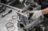
Additional valve components critical to operation include: valve seats (machined into the cylinder head), valve guides (supports valve stem movement), valve springs (return valves to closed position), valve rotators (reduce wear by rotating valves during operation), and valve seals (prevent oil leakage into combustion chamber).
2. Pre-Operational Inspection Checklist
Conduct a pre-operational inspection before starting the engine to identify early signs of valve degradation. This inspection should be completed daily for engines in continuous service, and before each start for standby generators:
Visual & Operational Checks
- Inspect valve cover gaskets for oil leaks (indicates potential valve seal failure).
- Check for abnormal engine noise (e.g., ticking, knocking) which may signal loose valve clearances or worn valve components.
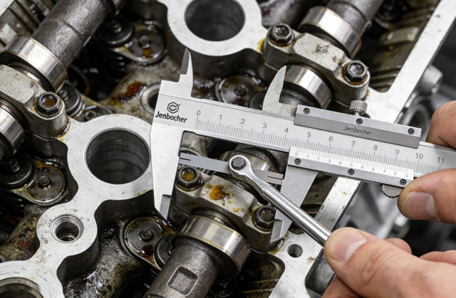
- Verify proper valve lash (clearance) using Jenbacher-specified feeler gauges—refer to the engine service manual for model-specific values (typically 0.20–0.40 mm for intake, 0.30–0.50 mm for exhaust).
- Examine exhaust gas temperature (EGT) readings—uneven EGT across cylinders may indicate stuck or leaking valves.
- Check oil consumption rates—elevated oil consumption can be caused by worn valve guides or damaged valve seals.
3. Routine Maintenance Procedures
Routine maintenance is critical to prevent premature valve failure. Follow Jenbacher’s recommended service intervals (adjust based on fuel quality and operating conditions):
3.1 Valve Clearance Adjustment (Every 2,000 Operating Hours)
Valve clearances change over time due to thermal expansion, wear, and spring fatigue. Incorrect clearances cause reduced engine efficiency, valve burning, or piston-to-valve contact (catastrophic damage):
- Shut down the engine and allow it to cool to ambient temperature (clearance measurements are temperature-dependent).
- Remove the valve cover and identify the intake/exhaust valves for each cylinder.
- Rotate the crankshaft to position the piston at Top Dead Center (TDC) for the cylinder being inspected (valve fully closed).
- Insert a feeler gauge between the valve stem and rocker arm to measure clearance.
- Loosen the locknut and adjust the adjusting screw to achieve the manufacturer’s specified clearance.
- Tighten the locknut and recheck clearance to confirm accuracy.
- Reinstall the valve cover with a new gasket and torque fasteners to Jenbacher specifications (typically 10–15 Nm).
3.2 Valve Seal & Guide Inspection (Every 4,000 Operating Hours)
Worn valve guides or damaged seals lead to oil contamination in the combustion chamber, increased emissions, and valve stem wear:
- Remove the valve spring and retainer to access the valve stem and guide.
- Measure valve stem-to-guide clearance using a dial indicator—excessive clearance (>0.15 mm for intake, >0.20 mm for exhaust) requires guide replacement.
- Inspect valve seals for cracks, hardening, or deformation—replace all seals if any damage is found (always use genuine Jenbacher OEM seals).
- Lubricate the valve stem with high-temperature engine oil before reinstallation to prevent scuffing.
3.3 Valve Spring Testing (Every 6,000 Operating Hours)
Weak or fatigued valve springs cause incomplete valve closure, leading to compression loss and valve burning:
- Remove valve springs and measure free length using a caliper—replace springs if length is reduced by >5% of the original specification.
- Test spring tension using a spring tester—ensure tension meets Jenbacher’s minimum load requirements at specified compressed length.
- Inspect springs for cracks, corrosion, or uneven coil spacing—replace immediately if defects are present.
4. In-Depth Valve Inspection (Major Service – 8,000–12,000 Operating Hours)
During major engine overhauls, remove the cylinder head to inspect valves for wear, damage, or deformation:
4.1 Key Inspection Criteria
| Valve Component | Inspection Checkpoints | Replacement Criteria |
|---|---|---|
| Valve Head | Wear on sealing face, pitting, burning, cracks, or deformation | Sealing face wear >0.5 mm, visible cracks, or burned areas |
| Valve Stem | Scuffing, corrosion, ovality, or wear at guide contact points | Stem diameter reduction >0.05 mm, or visible scuffing/corrosion |
| Valve Seat | Wear, pitting, or damage to sealing surface | Seat width exceeds specification, or pitting >0.2 mm deep |
| Valve Rotator | Free movement, corrosion, or broken components | Rotator does not spin freely, or structural damage |
4.2 Valve Refacing & Reconditioning
Minor valve wear can be corrected through reconditioning (only if within Jenbacher’s tolerance limits):
- Reface the valve sealing face using a valve grinding machine to restore a smooth, flat surface (maintain 30–45° seat angle per Jenbacher specs).
- Grind the valve stem tip to remove wear and ensure proper contact with the rocker arm.
- Lap the valve to the seat using abrasive compound to ensure a perfect seal (perform a leak test by pouring light oil over the valve—no leakage indicates a proper seal).
- Clean all components thoroughly to remove abrasive residue before reassembly.
5. Valve Replacement Guidelines
Replace valves (and matching seats/guides) when reconditioning is not feasible or when the following conditions are met:
- Valve head or stem has visible cracks (even minor cracks can propagate under thermal stress).
- Valve stem wear exceeds Jenbacher’s maximum tolerance limits.
- Valve head deformation or warping (causes poor sealing and compression loss).
- Exhaust valve corrosion from poor fuel quality (e.g., high sulfur content) that cannot be removed by cleaning.
- Valve has been reconditioned more than twice (material loss compromises structural integrity).
Always use Genuine Jenbacher OEM Valves for replacements. Aftermarket valves may not meet material or dimensional specifications, leading to premature failure and potential engine damage. Ensure replacement valves are matched to the engine model (e.g., J420 valves are not interchangeable with J620 valves).
6. Post-Maintenance Testing
After completing valve maintenance or replacement, perform the following tests to validate repairs:
- Compression Test: Measure cylinder compression pressure—uniform compression across all cylinders confirms proper valve sealing (low compression indicates leaks or incorrect clearances).
- Leak-Down Test: Introduce compressed air into the cylinder (piston at TDC) and measure air leakage—leakage >10% indicates valve or seat issues.
- Engine Break-In: Run the engine at 50% load for 1 hour to seat new valves and components—avoid full load during break-in.
- Operational Monitoring: Check EGT, oil consumption, and engine noise for 24 hours post-maintenance to confirm no issues.
7. Preventive Maintenance Best Practices
Minimize valve wear and extend service life with these preventive measures:
- Use only Jenbacher-approved fuel (proper filtration and treatment to reduce contaminants that cause valve wear).
- Maintain proper engine cooling system operation (overheating accelerates valve seat recession and valve warping).
- Ensure correct air-fuel ratio (rich mixtures cause carbon buildup on valves; lean mixtures cause valve burning).
- Replace air filters per schedule (dirty filters cause abrasive particles to enter the combustion chamber, damaging valves).
- Use high-quality engine oil that meets Jenbacher specifications (reduces valve guide wear and seal degradation).
- Avoid frequent cold starts (thermal shock to valves increases wear—use block heaters for cold-weather operation).
8. Troubleshooting Common Valve Issues
Address these common valve-related problems promptly to prevent secondary damage:
- Valve Burning: Caused by lean air-fuel mixture, incorrect clearances, or insufficient valve cooling. Correct air-fuel ratio, adjust clearances, and inspect valve cooling passages.
- Valve Sticking: Caused by carbon buildup (from poor fuel quality) or insufficient lubrication. Clean valves/ports, improve fuel filtration, and check oil supply to valve guides.
- Valve Float: Caused by weak valve springs or excessive engine RPM. Replace worn springs and ensure engine operates within rated RPM limits.
- Excessive Valve Noise: Caused by incorrect clearances, worn rocker arms, or loose fasteners. Adjust clearances and inspect rocker arm/pushrod components.