


The MWM speed sensor is a critical component in MWM engines, generator sets, industrial powertrains, and heavy-duty machinery. It monitors crankshaft or camshaft rotational speed, providing real-time data for engine control, fuel injection timing, speed regulation, and safety shutdown systems. Proper maintenance and timely repair of the MWM speed sensor are essential to ensure engine performance, fuel efficiency, operational reliability, and prevention of costly downtime.
This comprehensive guide covers routine maintenance practices, step-by-step inspection procedures, troubleshooting methods, repair solutions, replacement standards, and long-term care strategies for MWM speed sensors. All instructions are designed for field technicians, maintenance teams, and equipment operators to implement directly in industrial environments.
1. Disconnect the engine power supply and battery before inspection or repair.
2. Allow the engine to cool completely to avoid burns or heat damage.
3. Wear protective gear: gloves, safety goggles, and non-slip footwear.
4. Follow MWM engine manufacturer safety protocols and local industrial regulations.
1. Core Functions & Working Principle of MWM Speed Sensors
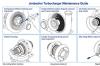
MWM speed sensors are typically inductive (passive) or Hall-effect (active) sensors, engineered to detect gear tooth passage on the crankshaft or flywheel. They convert mechanical rotation into electrical signals sent to the Engine Control Unit (ECU).
Primary Functions:
- Measure real-time engine RPM (revolutions per minute)
- Optimize fuel injection and ignition timing
- Enable over-speed protection and emergency shutdown
- Support transmission control and load regulation
- Diagnose engine misfires and mechanical irregularities
Operating Principle:
Inductive MWM speed sensors generate an AC voltage signal as gear teeth pass the sensor tip. Hall-effect sensors produce a stable digital DC signal. Signal loss, distortion, or weak output directly causes engine performance issues, stalling, or failure to start.
2. Routine Maintenance of MWM Speed Sensors
Routine maintenance prevents premature failure, extends sensor lifespan, and maintains consistent signal accuracy. Perform these tasks at scheduled intervals (per MWM engine service manuals: 500/1000/2000 operating hours).
2.1 Visual Inspection (Every 250 Operating Hours)
- Inspect the sensor housing for cracks, corrosion, physical damage, or oil contamination
- Check the wiring harness for fraying, cuts, pinching, or loose connections
- Examine the electrical connector for corrosion, bent pins, moisture, or debris
- Verify mounting bracket stability and absence of vibration damage
- Confirm no oil leaks or coolant seepage around the sensor mounting area
2.2 Cleaning & Contamination Removal (Every 500 Operating Hours)
- Use a clean, lint-free cloth and approved electrical contact cleaner to wipe the sensor tip
- Remove metal shavings, dirt, grease, oil, and carbon deposits from the sensor face (critical for signal accuracy)
- Clean the wiring connector with contact cleaner and dry completely with compressed air
- Do NOT use abrasive materials, harsh chemicals, or high-pressure water on the sensor
2.3 Air Gap Adjustment (Critical Maintenance Step)
The air gap (distance between sensor tip and gear teeth) is factory-calibrated for MWM engines. Deviation causes weak signals or sensor damage.
- Use a non-magnetic feeler gauge to measure the gap (standard: 0.8–1.2 mm for most MWM models)
- Loosen mounting bolts and adjust the gap to MWM specifications
- Tighten bolts to manufacturer torque settings to avoid over-tightening
- Recheck gap after adjustment to ensure stability
2.4 Wiring & Connection Maintenance
- Secure loose wiring with heat-resistant clips to avoid vibration damage
- Apply dielectric grease to connectors to prevent moisture and corrosion
- Repair minor wire damage with heat-shrink tubing (avoid electrical tape for long-term repairs)
- Ensure ground connections are clean, tight, and free of rust
3. Troubleshooting Faulty MWM Speed Sensors
MWM speed sensor failure triggers obvious engine symptoms. Use these diagnostic steps to identify issues quickly.
3.1 Common Failure Symptoms
- Engine stalling, rough idling, or difficulty starting
- Inaccurate RPM reading or no speed display on control panel
- ECU fault codes (e.g., speed signal loss, low signal voltage)
- Poor fuel efficiency and reduced engine power
- Over-speed shutdown malfunction or delayed response
- Transmission shifting issues (if integrated with drivetrain)
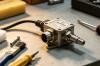
3.2 Step-by-Step Diagnostic Testing
- Visual Preliminary Check: Confirm no physical damage, oil contamination, or loose wiring
- Multimeter Testing (Inductive Sensors):
- Set multimeter to AC voltage; crank engine without starting
- Healthy sensor: 0.5–2.0 V AC output (varies by MWM model)
- No output = faulty sensor or broken wiring
- Resistance Testing:
- Disconnect sensor connector; measure internal resistance
- Standard range: 800–1500 ohms (MWM factory spec)
- 0 ohms (short) or infinite resistance (open) = defective sensor
- Hall-Effect Sensor Testing:
- Check 5V reference voltage from ECU
- Verify stable digital signal output during cranking
- No signal = sensor failure or ECU communication issue
- Air Gap Recheck: Confirm gap is within MWM tolerance
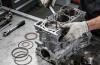
4. MWM Speed Sensor Repair Procedures
Minor damage can be repaired; severe failure requires full replacement. Follow these repair protocols for field servicing.
4.1 Repairable Issues & Solutions
- Contamination Buildup: Deep clean sensor tip and gear teeth; reinstall and adjust air gap
- Loose Connections: Tighten terminals, apply dielectric grease, secure harness
- Minor Wiring Damage: Solder broken wires, seal with heat-shrink tubing, insulate properly
- Incorrect Air Gap: Re-calibrate to MWM specifications and torque mounting bolts
- Connector Corrosion: Clean with contact cleaner, dry, and apply anti-corrosion grease
4.2 Non-Repairable Conditions (Replacement Required)
- Sensor housing cracks or internal coil damage
- Open/short circuit in internal circuitry
- Permanent signal loss or inconsistent output
- Corrosion of internal components
- Physical damage to sensor tip or mounting threads
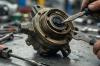
5. MWM Speed Sensor Replacement Guide
Use genuine MWM speed sensors or OEM-equivalent components for compatibility and reliability.
5.1 Replacement Steps
- Disconnect battery and ensure engine is cool
- Disconnect electrical connector gently (do not pull wires)
- Loosen mounting bolts and remove old sensor carefully
- Clean mounting surface and gear tooth area thoroughly
- Install new sensor; hand-tighten bolts first
- Set air gap to MWM factory specifications (0.8–1.2 mm)
- Tighten mounting bolts to recommended torque
- Reconnect wiring harness and secure with clips
- Perform startup test and verify RPM signal accuracy
- Clears ECU fault codes and run functional test
5.2 Post-Replacement Testing
- Start engine and check stable idle speed
- Monitor RPM display for accuracy
- Test acceleration and speed regulation
- Verify no fault codes on ECU
- Check for leaks or abnormal vibration around sensor
6. Long-Term Care & Lifespan Extension Tips
- Follow MWM’s official maintenance schedule strictly
- Protect sensors from oil, coolant, fuel, and moisture exposure
- Use dielectric grease on all electrical connections annually
- Inspect air gap after engine overhauls or major repairs
- Avoid physical impact or excessive vibration to the sensor
- Store spare sensors in dry, dust-free, anti-static packaging
- Train maintenance staff on proper handling and testing procedures
- Document all maintenance, repairs, and replacements for traceability
7. Conclusion
The MWM speed sensor is a small but mission-critical component that directly impacts engine performance, safety, and reliability. Routine visual inspection, professional cleaning, precise air gap adjustment, thorough wiring maintenance, and timely repair/replacement are the pillars of effective sensor care.
By following this comprehensive guide, you can minimize downtime, reduce maintenance costs, extend sensor and engine life, and ensure consistent operation of MWM-powered equipment. Always use genuine parts and adhere to MWM manufacturer specifications for optimal results.
Back to Top
