


Technical Maintenance Guide | Updated: March 2026
As the "brain" of Jenbacher gas engine systems, the Jenbacher Control Module (JCM) is responsible for monitoring engine operating parameters, outputting control commands, diagnosing faults, and coordinating system functions. Its operational stability directly determines engine start/stop, load regulation, and safety performance. During long-term high-load and complex operating conditions, the control module is prone to various faults due to environmental interference, component wear, improper operation, and other factors. Failure to troubleshoot and resolve these faults in a timely manner may lead to engine shutdown, performance degradation, and even equipment damage. Based on practical operation and maintenance experience, this article sorts out the most common fault types, causes, and targeted solutions of the Jenbacher control module to provide reference for on-site maintenance personnel, helping to quickly locate problems and efficiently restore normal equipment operation.
1. Core Fault Categories and Solutions
Faults of the Jenbacher Control Module mainly fall into four categories: power supply faults, signal transmission faults, software operation faults, and hardware damage faults. The following details the typical phenomena, possible causes, and troubleshooting steps for each type of fault. All operations must comply with equipment safety operating procedures, and the Lockout/Tagout (LOTO) process should be prioritized before power disconnection to avoid electric shock or equipment malfunction.
1.1 Power Supply Faults: Control Module Fails to Start or Restarts Frequently
Typical Phenomena: No indicator lights on the control module panel, no display on the screen; the module restarts immediately after startup, or suddenly goes black/powers off during operation; frequent "Power Supply Fault" prompts in fault logs.
Possible Causes:
- Abnormal input power supply, such as unstable 24V DC supply voltage (fluctuation exceeding ±10%), poor contact or disconnection of power supply lines;
- Blown internal fuse of the control module (usually 5A slow-blow fuse), mostly caused by instantaneous overcurrent or short circuit;
- Failed backup battery (3.6V lithium battery), unable to provide emergency power supply for module memory, resulting in configuration loss after power failure and failure to initialize normally after restart;
- Damaged internal power board of the module (e.g., bulging capacitors, burned rectifier chips), unable to convert input voltage into stable voltage required by the module.
Solutions:
- Step 1: Troubleshoot external power supply - Use a multimeter to measure the input power voltage and confirm it is within the standard range of 24V DC ±10%; check for loose or oxidized connectors/terminals of power supply lines, re-tighten terminals, clean oxide layers, and replace damaged power cables.
- Step 2: Check the fuse - Open the control module housing, locate the fuse at the power interface, and check if it is blown (visible through transparent housing, or measure continuity with a multimeter for opaque housing); if blown, replace with a genuine Jenbacher fuse of the same specification (5A slow-blow), do not use a larger specification fuse to avoid module damage.
- Step 3: Test the backup battery - Measure the backup battery voltage (normal range: 3.5-3.7V); if the voltage is below 3.3V, the battery is faulty and needs to be replaced with a genuine Jenbacher dedicated battery (recommended model: J987045). Pay attention to the polarity (positive/negative) during replacement to avoid reversing connections and damaging the memory module; restart the module after replacement and restore the previously backed-up configuration parameters.
- Step 4: Troubleshoot the internal power board - If the fault persists after the above operations and there is no obvious heating or odor from the module housing, the power board may be damaged. Contact a Jenbacher certified engineer to test or replace the power board; non-professionals are prohibited from disassembling internal module components.
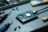
1.2 Signal Transmission Faults: No Sensor Feedback or Abnormal Data
Typical Phenomena: The control module displays no readings or drastically fluctuating readings for certain sensors (e.g., temperature, pressure, vibration sensors); the engine fails to adjust load normally or has ignition abnormalities; fault logs prompt "Sensor Signal Loss" or "Signal Distortion".
Possible Causes:
- Loose, disconnected, damaged, or short-circuited connecting lines between sensors and the control module, resulting in abnormal signal transmission;
- Faulty sensors (e.g., aging, damage, output signals beyond normal range, or expired calibration leading to drift);
- Damaged signal input interface of the control module, unable to receive sensor signals;
- On-site electromagnetic interference (e.g., frequency converters, high-voltage equipment) affecting signal transmission, leading to signal distortion.
Solutions:
- Step 1: Troubleshoot connecting lines - Disconnect the control module from the sensor, check for damaged/aged cables and loose/oxidized terminals; measure cable continuity with a multimeter to confirm no disconnection or short circuit; re-tighten terminals, clean oxidized terminals with a brass brush, and apply anti-corrosion grease (Jenbacher dedicated model: J620012).
- Step 2: Test the sensor itself - Remove the suspicious sensor, test its output signal with calibrated test equipment to confirm it is within the manufacturer's specified range; if the sensor output is abnormal, replace it with a genuine Jenbacher dedicated sensor, calibrate after replacement, and record calibration data.
- Step 3: Check the signal input interface - Measure the voltage and resistance of the control module's signal input interface with a multimeter to confirm no damage; if the interface is damaged, contact a Jenbacher certified engineer to replace the interface module (non-professionals are prohibited from disassembling).
- Step 4: Eliminate electromagnetic interference - Separate sensor cables from high-voltage cables and frequency converter lines by at least 30cm; install shielding layers for sensitive cables (ground one end of the shielding layer) to reduce electromagnetic interference; check the on-site grounding (ground resistance should be less than 4Ω).
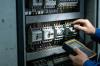
1.3 Software Operation Faults: Module Errors, Function Failure, or Communication Interruption
Typical Phenomena: Error codes displayed on the control module screen (e.g., "Software Error", "Configuration Corruption"); the module fails to communicate with external monitoring systems (SCADA, PLC) and cannot upload data; the control module cannot output ignition/fuel supply commands after engine startup; the software interface freezes or has no response to operations.
Possible Causes:
- Outdated control module software version, incompatible with engine firmware, leading to functional abnormalities;
- Lost or damaged configuration parameters (e.g., failure to back up after power failure, or configuration loss due to backup battery failure);
- Interrupted power supply during software update, resulting in incomplete software installation or system crash;
- Incorrect communication protocol settings or damaged communication ports (Ethernet, RS485), leading to communication failure with external systems;
- Damaged internal storage chip of the module, unable to store software programs and configuration parameters.
Solutions:
- Step 1: Back up existing configurations (if the module can start normally) - Connect to the control module via Jenbacher Service Tool (JST), back up current configuration parameters and fault logs to a dedicated storage device to avoid losing critical data during operations.
- Step 2: Software update and recovery - Download the latest software firmware from the official Jenbacher Service Portal (authenticated access required), connect to the module via JST, and execute the software update process; ensure stable power supply during the update (do not interrupt), and restart the module after completion; if the software crashes, restore factory settings via JST and re-import the previously backed-up configuration parameters.
- Step 3: Troubleshoot communication faults - Check communication protocol settings (e.g., IP address, port number, baud rate) to ensure consistency with external monitoring systems; test communication ports with network cables/RS485 cables and test equipment; if the port is damaged, contact a Jenbacher certified engineer to replace the communication module.
- Step 4: Test the storage chip - If the fault persists after restoring factory settings and updating software, and the module frequently loses configurations, the storage chip may be damaged. Contact Jenbacher factory service to replace the storage chip and reconfigure parameters.
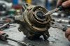
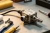
1.4 Hardware Damage Faults: Module Overheating, Component Burnout, or Complete Function Failure
Typical Phenomena: Severe heating of the control module housing (temperature exceeding 60℃) with odor or smoke; the module fails to start with all indicator lights off; complete failure of some functions (e.g., inability to output control commands or detect faults); bulging capacitors or loose solder joints on the internal circuit board.
Possible Causes:
- Cooling system faults (e.g., damaged cooling fan, blocked cooling vents), leading to poor heat dissipation and long-term overheating damage to internal components;
- Excessively high external voltage (e.g., lightning strikes, power surges), damaging internal circuit boards and chips;
- Aging internal components (e.g., capacitors, resistors, chips), leading to performance degradation and eventual damage;
- Foreign objects (e.g., dust, moisture) entering the module, causing short circuits or component corrosion.
Solutions:
- Step 1: Emergency treatment - If the module smokes or emits an odor, immediately cut off the external power supply and stop the engine to avoid fault expansion; wait for the module to cool completely before troubleshooting (prohibit operation when overheating or smoking).
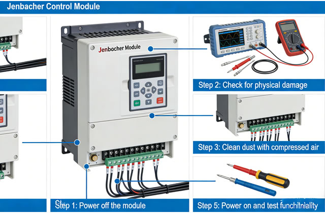
- Step 2: Troubleshoot the cooling system - Check if the module cooling fan is rotating normally (replace with genuine Jenbacher parts if not); clean dust/debris from cooling vents and heat sinks with compressed air (max 5bar) to ensure unobstructed heat dissipation; check the on-site ambient temperature (avoid long-term operation above 50℃), and improve control room ventilation if necessary.
- Step 3: Test internal hardware - Open the module housing and check for bulging capacitors, loose solder joints, or burned components on the circuit board; if obvious damage is found, prohibit self-replacement of components and contact Jenbacher factory service for comprehensive testing, repair, or replacement; if the module is damaged by lightning strikes/surges, check the on-site lightning protection device to prevent recurrence.
- Step 4: Preventive measures - Clean cooling vents weekly; conduct comprehensive internal module testing by Jenbacher factory service every 5 years and replace aging components in a timely manner; install lightning/surge protection devices around the module to ensure stable power supply.
2. Key Notes for Common Fault Troubleshooting
- Safety First: Implement the Lockout/Tagout (LOTO) process before all troubleshooting operations; confirm the module is completely powered off with no residual voltage before operation; avoid direct contact with internal circuit boards/chips to prevent electrostatic damage.
- Component Standardization: Use only genuine Jenbacher dedicated parts when replacing fuses, batteries, sensors, fans, etc. (do not use substitute parts) to avoid fault recurrence or equipment damage due to compatibility/quality issues.
- Record Tracking: After each troubleshooting/maintenance, record fault phenomena, troubleshooting processes, replaced parts, operation time, and test results in detail to establish a complete operation and maintenance archive for subsequent fault tracking and prevention.
- Professional Operation: Complex operations (e.g., software updates, hardware maintenance, parameter calibration) must be performed by Jenbacher certified engineers or qualified professionals (prohibit operation by non-professionals) to avoid serious faults caused by misoperation.
- Prevention-Oriented: Perform preventive maintenance (cleaning, inspection, calibration, replacement) in accordance with Jenbacher control module maintenance specifications to reduce fault probability; focus on the operating status of backup batteries, cooling systems, and sensors to identify potential hazards in advance.
3. Response Measures When Faults Cannot Be Resolved
If the fault cannot be resolved after the above troubleshooting, or if any of the following situations occur, contact Jenbacher technical support immediately to avoid fault expansion:
- Burned or smoking internal circuit boards of the module (unrepairable);
- Complete software system crash (cannot be resolved by restoring factory settings or updating software);
- Engine failure to start due to faults (core cause cannot be located after troubleshooting);
- Frequent unexplained fault errors affecting normal equipment operation.
When contacting Jenbacher technical support, provide the following information to facilitate quick problem location:
- Control module model, serial number, and software version;
- Engine model and operating hours;
- Fault phenomena (including error codes and screenshots);
- Implemented troubleshooting operations and results;
- Fault occurrence time and operating conditions (e.g., during startup, high-load operation).
24/7 Service Hotline: +43 7229 200 0
Email: [email protected]
Online Service Portal: https://service.jenbacher.com (authenticated access required)
4. Summary
Common faults of the Jenbacher Control Module are mainly related to power supply, signals, software, and hardware, with power supply and signal transmission faults accounting for the highest proportion and being mostly resolvable through on-site troubleshooting. In daily work, maintenance personnel should be familiar with the working principle and common fault characteristics of the control module, strictly follow safety operating procedures for troubleshooting and maintenance, and adopt a "from external to internal, from simple to complex" troubleshooting approach to reduce troubleshooting time. Meanwhile, strengthen preventive maintenance, regularly clean, calibrate, and replace vulnerable components to effectively reduce fault probability and ensure stable and safe operation of Jenbacher gas engine systems. For complex faults, contact Jenbacher professional technical support in a timely manner to avoid equipment damage due to improper operation and minimize downtime losses.

