


The Jenbacher camshaft is a core precision component in Jenbacher gas engines, responsible for controlling the timing, lift, and duration of intake and exhaust valve actuation. As a critical part of the engine’s valvetrain system, Jenbacher camshafts (forged from high-strength alloy steel with induction-hardened cam lobes) operate under extreme conditions: continuous rotational contact with valve lifters/followers, high thermal loads (up to 250°C in the valve train area), and cyclic mechanical stress. Improper maintenance of camshafts can lead to lobe wear, scoring, bending, or timing misalignment—resulting in reduced engine efficiency, increased emissions, valve train damage, and even catastrophic engine failure. This comprehensive guide outlines all critical aspects of Jenbacher camshaft maintenance, from pre-inspection preparation to long-term storage, to ensure optimal performance and extended service life.
1. Fundamental Understanding of Jenbacher Camshaft Design
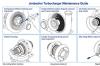
Jenbacher camshafts are engineered to meet the unique demands of gas-fueled engines, with design features tailored to J200, J400, J600, and J920 FleXtra models:
- Precision-machined cam lobes: Each lobe is shaped to control valve lift (typically 8–12 mm for Jenbacher engines) and duration (200–280 degrees of crankshaft rotation), optimized for gas combustion efficiency.
- Hardened surfaces: Cam lobes and journals feature induction hardening (hardness up to 58–62 HRC) to resist wear from contact with valve lifters/followers.
- Integrated gear/timing drive: The camshaft is driven by the crankshaft via a timing chain or gear system (1:2 speed ratio for 4-stroke engines), ensuring precise synchronization with piston movement.
- Oil supply passages: Drilled internal oil passages deliver pressurized lubrication to cam journals and lobes, reducing friction and dissipating heat.
- Cam bearing journals: Precision-ground journals (tolerance ±0.002 mm) support the camshaft in the cylinder head, with clearances optimized for oil film formation (0.020–0.035 mm).
These design characteristics demand maintenance practices that prioritize precision, lubrication, and adherence to Jenbacher OEM specifications—even minor deviations (e.g., incorrect valve clearance, poor lubrication) will accelerate cam lobe wear and compromise engine performance.
2. Pre-Maintenance Preparation: Safety & Tooling
Camshaft maintenance involves disassembling the valve train and handling precision components (a Jenbacher J600 camshaft weighs 35–45 kg). Proper preparation is critical to avoid accidents, component damage, or inaccurate inspections.
2.1 Non-Negotiable Safety Protocols
- Complete engine shutdown & isolation: Shut down the engine, disconnect all power sources (electrical, fuel, gas), and lock out/tag out (LOTO) all systems to prevent accidental startup. Allow the engine to cool fully (4–6 hours) to avoid thermal expansion-related measurement errors and burn risks.
- Controlled workspace: Clear the area of debris, flammable materials, and loose tools. Use anti-slip mats for footing, and ensure adequate ventilation (especially when using solvent-based cleaners). Wear PPE: nitrile gloves (prevent oil contamination/skin irritation), safety glasses (protect from debris), and mechanic gloves (for handling sharp edges).
- Valve train safety: Before removing the camshaft, relieve valve spring pressure using a valve spring compressor (Jenbacher-specified tool) to prevent valve damage or accidental movement.
- Component labeling: Label all valve train components (lifters, followers, pushrods) with their original positions to ensure correct reassembly—misalignment will cause uneven cam lobe wear.
2.2 Essential Tools for Camshaft Maintenance
- Precision measuring tools: Micrometer set (0.001 mm resolution) for lobe height/diameter measurement, feeler gauges (0.01–1.0 mm) for valve clearance checks, dial indicator (for runout/bending checks), and surface roughness tester (Ra/Rz scale).
- Cleaning supplies: Low-residue solvent (Jenbacher-approved degreaser), ultrasonic cleaner (for oil passage cleaning), soft-bristle nylon brushes (non-abrasive), lint-free microfiber cloths, and compressed air (oil-free, 60–80 PSI).
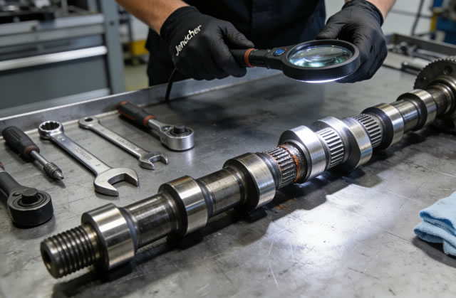
- Inspection equipment: Magnetic Particle Inspection (MPI) kit (detect surface cracks on lobes/journals), magnifying lamp (10–20x magnification), and hardness tester (for lobe surface hardness verification).
- Assembly tools: Valve spring compressor (OEM-spec), torque wrench (calibrated to Jenbacher specs, 1/4” or 3/8” drive), camshaft installation tool (to prevent bearing damage), and assembly lube (Jenbacher PN: 000123457).
- Support equipment: Camshaft stand (soft-jawed to prevent journal damage), V-blocks (precision-ground), and timing alignment tools (OEM-spec for cam/crank synchronization).
3. Comprehensive Inspection Procedures
Camshaft inspection is the cornerstone of maintenance—defects must be identified early to prevent progressive damage. Inspections should be performed during every major engine overhaul (8,000–12,000 operating hours) or if abnormal symptoms (e.g., valve train noise, reduced power) are detected.
3.1 Initial Visual & Cleaning Checks
Before detailed measurement, thoroughly clean the camshaft to remove oil, carbon, and debris—contamination masks defects and skews measurements:
- Wipe external surfaces with solvent-soaked microfiber cloths; use nylon brushes to remove carbon deposits from cam lobes and journals (avoid steel wool or abrasive pads that scratch hardened surfaces).
- Clean internal oil passages with compressed air and solvent—blockages restrict lubrication and cause journal/lobe overheating. Verify passage patency by blowing air through one end and checking for consistent airflow at the other.
- Dry the camshaft completely with compressed air (low pressure to avoid surface damage) and lint-free cloths. Ensure no solvent residue remains (it can degrade bearing lubrication).
3.2 Dimensional Inspection (Critical Tolerances)
Measure cam lobes and journals to check for wear, out-of-roundness, or bending—compare results to Jenbacher OEM specifications (example values for J600 engine):
- Cam lobe height: Measure the maximum height of each lobe (standard: 38.000 mm ± 0.002 mm). Wear exceeding 0.10 mm (lobe height reduction) requires camshaft replacement—lobe regrinding is not recommended for Jenbacher camshafts (compromises hardness and lobe shape).
- Cam journal diameter: Measure each journal (standard: 50.000 mm ± 0.002 mm) at 3 points (0°, 90°, 180°). Wear exceeding 0.02 mm or out-of-roundness > 0.003 mm indicates journal damage.
- Radial runout (bending check): Mount the camshaft on V-blocks; use a dial indicator to measure radial runout at each journal. Maximum allowable runout is 0.05 mm for Jenbacher camshafts—values above indicate bending, which causes uneven valve lift and lobe wear.
- Valve clearance verification: Check valve clearance (cold engine: intake 0.20–0.25 mm, exhaust 0.30–0.35 mm for Jenbacher engines) using feeler gauges. Incorrect clearance causes excessive lobe wear and valve train noise.
3.3 Surface Defect Inspection
Even minor surface defects on cam lobes can propagate into fatal cracks under cyclic loading—use MPI to detect hidden damage:
- Cam lobe surfaces: Look for scoring, pitting, galling, or heat discoloration (blue/brown hues indicate overheating). Scratches deeper than 0.01 mm on lobe contact surfaces accelerate wear and reduce valve control precision.
- Journal surfaces: Inspect for scoring, corrosion, or bearing material transfer (indicates inadequate lubrication or bearing failure).
- Timing gear/chain drive teeth: Check gear teeth for wear, chipping, or pitting—damaged teeth cause timing misalignment and camshaft vibration.
- Oil passage openings: Check for burrs or blockages around passage exits—burrs can damage bearings and restrict oil flow to lobes/journals.
3.4 Lubrication System Compatibility Check
Camshaft failure is often linked to inadequate lubrication—verify the engine’s lubrication system supports the camshaft:
- Test oil pressure (Jenbacher spec: 3–5 bar at idle, 8–10 bar at operating speed) to ensure sufficient flow to cam journals and lobes.
- Analyze used oil for metal particles (via spectrometric oil analysis)—elevated iron/steel levels indicate cam lobe/journal wear.
- Inspect oil filters and passages for clogs—debris in the lubrication system causes abrasive wear on cam surfaces.
- Verify oil viscosity (Jenbacher-spec 10W-40 or 15W-40 synthetic oil)—incorrect viscosity reduces oil film strength and accelerates wear.
4. Repair & Refinishing Guidelines
Minor camshaft wear can be addressed via precision refinishing—severe damage requires replacement (never attempt makeshift repairs like welding or filing):
- Lobe polishing: For minor scratches/scoring (< 0.01 mm) on lobe surfaces, polish with fine emery cloth (1000–1200 grit) in the direction of rotation (avoid cross-hatching). Finish with a honing stone to restore surface roughness (Ra 0.2–0.4 μm, per Jenbacher specs).
- Journal reconditioning: For minor journal wear (< 0.02 mm), regrind journals to Jenbacher’s undersize tolerances (e.g., -0.25 mm, -0.50 mm) and use matching undersize cam bearings (OEM-specified).
- Valve clearance adjustment: Correct valve clearance (per OEM specs) to reduce excessive lobe contact pressure—this is the most effective way to prevent premature lobe wear.
- Rejection criteria: Replace the camshaft if: lobe wear exceeds 0.10 mm, radial runout > 0.10 mm, surface hardness < 55 HRC, cracks are detected (any size), or gear teeth are damaged/chipped.
5. Assembly & Installation Best Practices
Incorrect assembly is a leading cause of post-maintenance camshaft failure—follow these steps strictly:
- Cleanliness first: Ensure the cylinder head, cam bearings, and camshaft are free of debris, oil residue, or fingerprints (skin oils cause corrosion). Assemble in a dust-free environment.
- Pre-lubrication: Apply a thick layer of Jenbacher assembly lube to cam lobes, journals, and bearings—never install a dry camshaft (causes instant wear on startup).
- Camshaft installation: Use a camshaft installation tool to guide the camshaft into the cylinder head (avoid forcing the camshaft, which can damage bearings and lobes). Ensure all journals seat fully on bearings without binding.
- Timing alignment: Align the camshaft timing marks with the crankshaft timing marks (per Jenbacher manual) to ensure correct valve timing. Verify alignment with a dial indicator (valve lift at TDC should match OEM specs).
- Cam bearing cap torque: Tighten cam bearing caps in a sequential pattern (from center to ends) to OEM specs (e.g., 25–30 Nm for Jenbacher J600). Use a torque wrench with a 1/4” drive for precision.
- Valve clearance adjustment: After installation, adjust valve clearance (cold engine) to Jenbacher specs—incorrect clearance causes excessive lobe wear and valve train noise.
- Post-assembly rotation test: Rotate the engine by hand (using a crankshaft turning tool) to ensure smooth valve train operation with no resistance or grinding noises. Any stiffness indicates misalignment or incorrect clearance.
6. Long-Term Storage & Preservation
Camshafts removed from engines for extended storage (> 3 months) require proper preservation to prevent corrosion and damage:
- Clean & dry: Thoroughly clean all surfaces and oil passages; dry completely (use heated air if needed) to remove moisture.
- Corrosion protection: Apply a thick layer of Jenbacher anti-corrosion grease (PN: 000789012) to cam lobes, journals, and gear teeth. For long-term storage (> 6 months), wrap the camshaft in VCI (Vapor Corrosion Inhibitor) paper and seal in a moisture-proof plastic bag.
- Proper support: Store the camshaft horizontally on a dedicated stand with soft, non-abrasive supports at the cam journals (avoid supporting on lobes to prevent deformation).
- Storage environment: Keep in a cool, dry area (temperature 10–25°C, humidity < 60%) away from direct sunlight, corrosive chemicals (acids, solvents), and extreme temperature fluctuations.
- Regular inspection: Inspect stored camshafts every 6 months—reapply anti-corrosion grease if it dries/cracks, and check for signs of rust or damage.
7. Preventive Maintenance Best Practices
Proactive maintenance extends camshaft service life (target: 20,000+ operating hours for Jenbacher camshafts):
- Adhere to oil change intervals: Replace engine oil (Jenbacher-spec synthetic oil) every 2,000 operating hours—old oil loses lubricity and increases cam lobe wear.
- Maintain proper valve clearance: Check and adjust valve clearance every 5,000 operating hours (or during routine overhauls)—incorrect clearance is the #1 cause of cam lobe wear.
- Use OEM valve train components: Only use Jenbacher original lifters, followers, and pushrods—non-OEM components have inconsistent hardness and cause uneven lobe wear.
- Monitor engine temperature: Avoid overheating (engine temperature > 95°C)—high temperatures degrade oil quality and accelerate cam lobe wear.
- Regular valve train inspections: Inspect cam lobes, lifters, and pushrods every 8,000 operating hours—early detection of wear prevents costly repairs.
- Document all maintenance: Keep a log of camshaft inspections, measurements, repairs, and operating hours—this helps track wear patterns and plan overhauls.
8. Replacement Criteria (Non-Negotiable)
Replace the Jenbacher camshaft immediately if any of the following conditions are met:
| Failure Condition | Rationale for Replacement |
|---|---|
| Cam lobe wear > 0.10 mm (height reduction) or severe scoring/pitting | Worn lobes cause incorrect valve lift/duration, reducing engine efficiency and increasing emissions. |
| Radial runout > 0.10 mm (camshaft bending) | Bending causes uneven valve lift, lobe wear, and valve train damage. |
| Fatigue cracks (detected via MPI) on lobes, journals, or gear teeth | Cracks propagate rapidly under cyclic loading, leading to camshaft fracture and engine destruction. |
| Surface hardness < 55 HRC (cam lobe surfaces) | Loss of hardness drastically reduces wear resistance and fatigue life. |
| Damaged timing gear/chain drive teeth (chipping, wear, or pitting) | Damaged teeth cause timing misalignment, valve/piston collision, and catastrophic engine failure. |
| Cam journal wear > 0.02 mm or irreparable scoring | Worn journals cause camshaft vibration, bearing failure, and oil pressure loss. |
Final Summary
Jenbacher camshafts are the “brain” of the engine’s valvetrain system, controlling the critical timing of intake and exhaust valves for optimal gas combustion efficiency. Their maintenance requires uncompromising attention to precision, lubrication, and OEM specifications. By following the guidelines outlined—rigorous pre-inspection preparation, detailed dimensional/surface defect checks, proper repair/refinishing (only by certified shops), and strict assembly/timing protocols—you can maximize camshaft service life, prevent valve train damage, and ensure consistent engine performance.
Always prioritize OEM parts and Jenbacher-authorized service for critical repairs, and implement preventive maintenance (regular valve clearance checks, oil analysis) to detect issues early. A well-maintained Jenbacher camshaft not only reduces downtime and repair costs but also safeguards the entire engine system from secondary damage, ensuring reliable operation for years to come.