


Official Guidelines for Reliable Operation of Jenbacher Engine Pressure Sensing Systems
1. Introduction to Jenbacher Gas Pressure Sensors
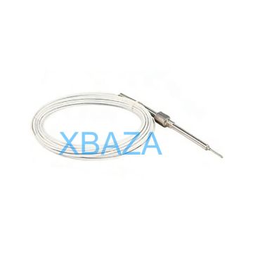
Jenbacher gas pressure sensors are critical components in Jenbacher gas engine systems, responsible for accurately measuring fuel gas pressure (natural gas, biogas, landfill gas) at key points in the fuel supply chain—including gas intake, pre-mixing, and combustion chambers. These sensors provide real-time data to the engine control unit (ECU), enabling precise fuel-air ratio adjustment and ensuring optimal combustion efficiency, emissions compliance, and engine safety.
Common Jenbacher pressure sensor models include: 419828, 426266, 588100, and the JEMS series (Jenbacher Engine Monitoring System) pressure transducers.
2. Pre-Maintenance Safety Protocols
- Isolate the gas supply: Close all upstream and downstream isolation valves for the sensor’s fuel gas line. Implement Lockout/Tagout (LOTO) procedures on all valves to prevent accidental activation.
- Depressurize the system: Vent residual gas from the sensor manifold and associated piping in accordance with local safety regulations. Use a calibrated gas detector to confirm 0% LEL (Lower Explosive Limit) before beginning work.
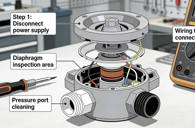
- Disconnect power: Cut off electrical power to the sensor (12V/24V DC or 4-20mA signal circuit) at the main control panel. Secure with LOTO tags to prevent power restoration during maintenance.
- Wear appropriate PPE: Mandatory personal protective equipment includes: flame-retardant clothing, chemical-resistant gloves, safety glasses with face shield, gas detection monitor (LEL/CO/H2S), and anti-static footwear. Respiratory protection is required in confined spaces or high gas concentration areas.
- Verify no ignition sources: Ensure the work area is free of open flames, sparks, or hot surfaces. Use only intrinsically safe tools (ATEX/IECEx certified) in classified hazardous areas.
3. Routine Maintenance Procedures
3.1 Daily Inspection Checklist
- Visual inspection for physical damage (cracks, dents, loose fittings) on the sensor body and wiring harness
- Check for gas leaks at sensor process connections (use soap solution or ultrasonic leak detector)
- Verify stable signal output on the ECU/JEMS display (no erratic pressure readings or "sensor fault" codes)
- Inspect electrical connectors for corrosion, moisture ingress, or loose pins
- Check mounting hardware for tightness and signs of vibration damage
3.2 Weekly Maintenance
- Clean the sensor’s pressure port and diaphragm with compressed air (max 30 psi) to remove dust, debris, or condensate buildup (do not use high-pressure air directly on the diaphragm).
- Inspect the wiring harness for abrasion, cuts, or insulation damage; repair or replace damaged wiring immediately.
- Test sensor response time: Use the ECU to trigger a pressure change (via a calibrated regulator) and confirm the sensor updates readings within 100ms (per Jenbacher spec).
- Check ground connections for corrosion; clean and retighten if necessary (torque to 8-10 Nm).
3.3 Monthly Maintenance
- Disconnect the sensor’s electrical connector and clean pins with contact cleaner (Jenbacher part no. 410012) to remove oxidation or moisture.
- Inspect the sensor’s process connection (NPT/BSPP thread) for thread damage, corrosion, or seizing; apply anti-seize compound (high-temperature, anti-galling, Jenbacher-approved: 401055) to threads if needed.
- Verify sensor mounting torque:
- 1/2" NPT/BSPP: 35-40 Nm (26-30 ft-lbs)
- 3/4" NPT/BSPP: 55-60 Nm (41-44 ft-lbs)
- 1" NPT/BSPP: 75-80 Nm (55-59 ft-lbs)
- Perform a zero-point check: Isolate the sensor from pressure, vent the pressure port to atmosphere, and confirm the ECU displays 0 mbar (or calibrated zero value). Adjust via the sensor’s zero trim potentiometer if necessary (per Section 4).
- Record all readings in the Jenbacher Service Log (Form No. JSL-004) for trend analysis and predictive maintenance.
3.4 Quarterly Preventive Maintenance
- Remove the sensor from the process line (follow Section 2 safety protocols) and clean the pressure diaphragm with a lint-free cloth dampened in isopropyl alcohol (do not use harsh solvents).
- Inspect the sensor’s O-ring/gasket (part no. 412345) for wear, cracking, or hardening; replace if damaged (always use Jenbacher OEM gaskets).
- Calibrate the sensor (see Section 4 for full calibration procedure) to ensure accuracy within ±0.5% of full scale (per Jenbacher specifications).
- Test the sensor’s temperature compensation: Verify readings remain stable across the operating temperature range (-20°C to +85°C) using a temperature-controlled test chamber.
- Inspect the sensor’s protective housing (IP67/IP68 rating) for water ingress; replace the housing seal if compromised.
3.5 Annual Maintenance
- Complete disassembly of the sensor manifold (if applicable) and clean all internal components with non-abrasive, alcohol-based cleaner.
- Replace all wear parts: O-rings, gaskets, and electrical connector seals (Jenbacher Seal Kit: 420033).
- Perform a full functional test (zero, span, linearity) using a calibrated pressure calibrator (e.g., Fluke 718Pro or WIKA CPH6000).
- Verify compliance with Jenbacher’s performance specifications (see Section 5 for reference).
- Replace the sensor if it fails to meet calibration standards (sensor lifespan is typically 5-7 years in normal operating conditions).
4. Sensor Calibration Procedure
- Preparation:
- Disconnect the sensor from the gas line and mount it on a calibration bench.
- Connect the calibrator’s pressure port to the sensor’s process connection using a leak-tight adapter (NPT/BSPP to calibrator fitting).
- Connect the sensor’s electrical output (4-20mA) to a multimeter or calibrator with current measurement capability.
- Apply nominal voltage to the sensor (12V/24V DC per sensor spec).
- Zero Calibration:
- Vent the sensor’s pressure port to atmospheric pressure (0 mbar/g).
- Allow the sensor to stabilize for 5 minutes at room temperature (20-25°C).
- Adjust the zero trim potentiometer (on sensor housing) until the output signal is 4.00 mA (0% of full scale).
- Span Calibration:
- Apply the sensor’s full-scale pressure (e.g., 0-1000 mbar, 0-5000 mbar—per sensor model) using the calibrator.
- Stabilize for 3 minutes and adjust the span trim potentiometer until the output signal is 20.00 mA (100% of full scale).
- Linearity Check:
- Apply 25%, 50%, and 75% of full-scale pressure and record the output current.
- Deviation from the expected value (10 mA, 12 mA, 16 mA) must not exceed ±0.5% of full scale (per Jenbacher spec).
- Repeat zero and span calibration if linearity error exceeds limits.
- Final Verification:
- Cycle pressure from 0 to full scale 3 times to confirm stable readings.
- Disconnect the calibrator, reinstall the sensor, and perform a leak test (Section 6).
- Update the sensor’s calibration sticker with date, technician name, and next calibration due date (12 months).
5. Technical Specifications (Reference)
Jenbacher Standard Pressure Sensor Specifications
| Parameter | Specification |
|---|---|
| Operating Voltage | 12-24 V DC (±10%) |
| Output Signal | 4-20 mA (2-wire/3-wire configuration) |
| Accuracy | ±0.5% of full scale (25°C) |
| Operating Temperature Range | -20°C to +85°C (-4°F to +185°F) |
| Pressure Range (Common) | 0-100 mbar, 0-500 mbar, 0-1000 mbar, 0-5000 mbar |
| Process Connection | 1/2" NPT, 3/4" BSPP (male/female) |
| Protection Rating | IP67 / IP68 (submersible up to 1m) |
| Response Time | < 100 ms (90% step change) |
6. Common Faults and Repair Solutions
| Fault Symptom | Root Cause | Repair/Resolution Steps |
|---|---|---|
| Erratic pressure readings (fluctuating values) | 1. Condensate buildup in pressure port 2. Loose electrical connections 3. Diaphragm damage 4. Electromagnetic interference (EMI) |
1. Clean pressure port with isopropyl alcohol and install a condensate trap 2. Reconnect and secure electrical connectors (torque 2-3 Nm) 3. Replace sensor (damaged diaphragm cannot be repaired) 4. Route wiring away from high-voltage cables; install EMI filter (Jenbacher part 418999) |
| No signal output (0 mA or open circuit) | 1. Power supply failure 2. Broken wiring harness 3. Internal sensor electronics failure 4. Short circuit in signal wire |
1. Test power supply at sensor terminals (12/24V DC) 2. Repair/replace damaged wiring (use heat-shrink tubing) 3. Replace sensor (internal electronics are not serviceable) 4. Check for short to ground and repair |
| Constant full-scale reading (20 mA) | 1. Overpressure damage to diaphragm 2. Span potentiometer failure 3. ECU configuration error |
1. Replace sensor (overpressure damage is permanent) 2. Recalibrate or replace sensor 3. Verify ECU pressure range settings match sensor specs |
| Gas leak at process connection | 1. Worn/damaged O-ring/gasket 2. Improper torque on mounting threads 3. Thread damage/corrosion |
1. Replace O-ring/gasket (Jenbacher OEM part 412345) 2. Retorque to spec (35-80 Nm per thread size) 3. Repair/replace damaged threads or sensor housing |
| Slow response time (> 200 ms) | 1. Clogged pressure port 2. Temperature drift (extreme ambient temp) 3. Aging sensor electronics |
1. Clean pressure port with compressed air 2. Install heat shield or relocate sensor to moderate temp area 3. Replace sensor (end-of-life component) |
7. Post-Repair/Calibration Verification
After completing maintenance, calibration, or repair, perform the following verification steps to ensure safe and reliable operation:
- Reconnect all electrical and process connections (torque to spec) and remove all LOTO tags.
- Perform a gas leak test: Pressurize the system to operating pressure (e.g., 200-500 mbar) and check all connections with a calibrated gas detector or soap solution. No bubbles or gas detection = pass.
- Restore power to the sensor and verify signal output on the ECU/JEMS display:
- Atmospheric pressure: ~4 mA (0 mbar)
- Operating pressure: Corresponding mA value (e.g., 10 mA = 25% full scale)
- Run the engine in idle mode for 30 minutes and monitor sensor readings:
- No sudden fluctuations (±5 mbar)
- No error codes (e.g., "P0191" – Fuel Rail Pressure Sensor Circuit Range/Performance)
- Stable engine performance (no misfires, rough idle)
- Document all work in the Jenbacher Service Log:
- Date, technician name, work performed (inspection/calibration/repair)
- Calibration data (zero/span readings, linearity results)
- Parts replaced (part numbers, quantities)
- Leak test results and engine run test data
8. Spare Parts and Technical Support
Always use genuine Jenbacher OEM parts for repairs and replacements. Non-OEM parts may void the warranty, cause inaccurate readings, or fail prematurely in harsh operating conditions.
- Key spare parts for Jenbacher pressure sensors:
- O-Ring/Gasket Kit: 412345
- Electrical Connector: 419899
- Anti-Seize Compound: 401055
- Contact Cleaner: 410012
- Replacement Sensor (Model 419828): 419828
- Authorized Jenbacher Support Channels:
- Jenbacher Technical Support: +43 7229 2000 (Austria)
- Jenbacher Online Parts Portal: https://www.ge-energy.com/jenbacher-parts
- Jenbacher Service Manuals: https://www.ge-energy.com/jenbacher-service