





1. Overview of MWM Automatic Voltage Regulator (AVR)
The MWM Automatic Voltage Regulator (AVR) is a critical control component for MWM diesel/gas generator sets, responsible for stabilizing output voltage, adjusting excitation current, and protecting the generator from overvoltage, undervoltage, overload, and short-circuit faults. It ensures stable, reliable, and high-quality power output for industrial, commercial, and emergency power systems.
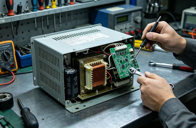
Regular maintenance and timely repair of the MWM AVR extend its service life, reduce generator downtime, lower operational costs, and avoid unexpected power failures. This guide covers routine maintenance, periodic inspection, fault diagnosis, repair procedures, and storage recommendations for MWM AVR units.
2. Routine Maintenance (Daily/Weekly Inspection)
Routine maintenance is the foundation of reliable AVR performance and should be performed without dismantling the unit, ideal for daily operator checks.
2.1 Visual & Environmental Inspection
- Check the AVR housing for cracks, deformation, burn marks, or water seepage; replace damaged housings immediately
- Verify the installation location is dry, dust-free, and well-ventilated (no corrosive gas, oil mist, or high humidity)
- Ensure the AVR is securely mounted with no loose brackets or vibration issues
- Inspect cable connections for wear, cracking, or exposed copper wires
2.2 Connection & Terminal Check
- Tighten all terminal screws (excitation, voltage sensing, power input, load output) to factory torque specifications
- Clean terminal oxidation, oil stains, and dust with a dry, lint-free cloth or contact cleaner
- Check for loose wiring, poor contact, or overheating discoloration at terminals
- Confirm wiring matches the MWM AVR schematic diagram (no wrong connections or reversed polarity)
2.3 Operational Status Monitoring
- Monitor generator output voltage (stable at rated value, no fluctuation or deviation)
- Listen for abnormal noise or vibration from the AVR unit
- Check surface temperature (no overheating; normal operating temperature: -20°C to +60°C)
- Verify indicator lights (LEDs) function normally per manufacturer specifications
3. Periodic Maintenance (Monthly/Quarterly/Annual Service)
Periodic maintenance requires professional tools and qualified technicians, performed at fixed intervals to detect hidden faults early.
3.1 Monthly Maintenance
- Deep clean the AVR circuit board with compressed air (dry, oil-free) or anti-static brush
- Re-torque all electrical terminals and connectors
- Test voltage regulation accuracy (compare measured voltage with rated voltage)
- Check ventilation slots and heat sinks for blockages
3.2 Quarterly Maintenance
- Inspect circuit board for trace damage, cold solder joints, or component bulging
- Test protection functions: overvoltage, undervoltage, over-excitation, and loss-of-excitation protection
- Calibrate voltage setting knobs/potentiometers to eliminate drift
- Measure insulation resistance (≥1MΩ between terminals and chassis; replace if lower)
3.3 Annual Comprehensive Maintenance
- Full disassembly inspection (follow MWM official disassembly steps)
- Replace aging components: capacitors, resistors, diodes, and transistors
- Perform full-load test to verify voltage stability under 100% rated load
- Update firmware/software (for digital MWM AVR models)
- Create maintenance records: test data, replaced parts, and calibration results
4. Common Faults & Professional Repair Procedures
Below are the most frequent MWM AVR failures, root causes, and step-by-step repair solutions:
4.1 No Output Voltage / Generator Fails to Build Voltage
Possible Causes: Blown fuse, damaged excitation diode, open circuit in field winding, faulty voltage sensing circuit, dead capacitor
Repair Steps:
- Replace blown fuse with the same rating (do not overrate)
- Test excitation diodes with a multimeter; replace shorted/open diodes
- Check field winding continuity and insulation; repair or replace winding
- Reconnect or replace faulty voltage sensing wires
- Replace failed filter/starting capacitors
- Perform flash field procedure to restore residual magnetism
4.2 Unstable/Fluctuating Output Voltage
Possible Causes: Loose sensing wiring, worn potentiometer, dirty circuit board, faulty voltage regulator chip, unstable generator speed
Repair Steps:
- Secure all voltage sensing connections
- Clean or replace damaged adjustment potentiometers
- Deep clean PCB with isopropyl alcohol and dry completely
- Replace damaged regulator ICs or control modules
- Adjust generator engine speed to rated RPM
- Recalibrate AVR voltage setpoint
4.3 Overvoltage / Undervoltage Output
Possible Causes: Incorrect calibration, faulty reference voltage circuit, damaged excitation transistor, incorrect wiring
Repair Steps:
- Recalibrate AVR using MWM calibration tools
- Replace reference voltage components (zener diodes, regulators)
- Replace shorted/open excitation transistors/MOSFETs
- Recheck wiring against schematic and correct errors
4.4 AVR Overheating & Burnout
Possible Causes: Poor ventilation, overload, short-circuit in excitation circuit, high ambient temperature
Repair Steps:
- Clean heat sinks and cooling fans
- Reduce generator load to rated capacity
- Repair shorted excitation coils or wiring
- Improve ventilation or add cooling systems
- Replace burned circuit boards or entire AVR unit
4.5 Protection System Malfunction
Possible Causes: Faulty sensor, damaged protection chip, parameter drift, loose ground wire
Repair Steps:
- Test and replace faulty voltage/current sensors
- Replace damaged protection integrated circuits
- Reset protection parameters to factory settings
- Secure and repair grounding connections
5. Component Replacement Standards
- Only use genuine MWM AVR replacement parts or OEM-equivalent components
- Capacitors: replace electrolytic capacitors every 3–5 years (high-temperature environment: 2–3 years)
- Diodes & Transistors: replace with identical voltage/current ratings
- PCBs: replace cracked, burned, or severely corroded boards
- Connectors & Cables: replace oxidized, brittle, or overheated wiring harnesses
6. Post-Repair Testing & Commissioning
- Reconnect all wiring correctly and double-check connections
- Perform no-load test: verify stable voltage output
- Apply 50% → 75% → 100% load test gradually
- Test all protection functions (trigger manually to confirm tripping)
- Record voltage values, temperature, and running status for 1–2 hours
- Confirm no abnormal noise, overheating, or voltage deviation
7. Long-Term Storage & Preservation
- Store AVR in dry, dust-free, ventilated environment (humidity: 40%–60%)
- Cover with anti-static packaging to avoid moisture and corrosion
- Discharge capacitors completely before storage
- Inspect stored units every 6 months; clean and dry if needed
- Do not store with corrosive chemicals, oils, or strong magnetic equipment
8. Maintenance Records & Documentation
Accurate records are critical for troubleshooting and lifecycle management. Record the following for every service:
- Date of maintenance and technician name
- AVR model number and generator serial number
- Inspection items and test data
- Replaced components and part numbers
- Fault description and root cause
- Calibration results and post-repair performance

