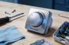


1. Overview of MWM Control Module
The MWM Control Module is a core electronic component widely used in MWM diesel/gas engines, generator sets, industrial power systems, and marine propulsion equipment. It serves as the "brain" of the entire engine system, responsible for real-time monitoring, parameter adjustment, fault diagnosis, load control, and safety protection.
Stable operation of the MWM Control Module directly determines engine performance, fuel efficiency, emission compliance, and service life. Regular maintenance and professional repair can avoid unexpected downtime, reduce operating costs, and extend the service life of the module and the entire engine system.
- Disconnect all power supplies (main power, backup power, and battery) before any operation
- Allow the engine and control module to cool down completely to avoid high-temperature injury
- Use anti-static tools and wear anti-static wrist straps to prevent ESD damage to circuit boards
- Do not touch internal components with bare hands or wet/dirty gloves
- Follow local electrical safety standards and equipment manufacturer guidelines
2. Routine Preventive Maintenance Schedule
Preventive maintenance is the most effective way to avoid failures. Below is the standardized maintenance cycle recommended for MWM Control Modules:
| Maintenance Cycle | Key Tasks |
|---|---|
| Daily Inspection | Check indicator lights, display status, alarm codes, and abnormal noise/odor |
| Weekly Maintenance | Clean surface dust, check cable connections, verify communication stability |
| Monthly Calibration | Calibrate sensors, test protection functions, backup configuration parameters |
| Quarterly Deep Maintenance | Internal dust cleaning, terminal tightening, voltage detection, firmware check |
| Annual Overhaul | Full component inspection, capacitor testing, circuit board detection, performance verification |
3. Step-by-Step Routine Maintenance Procedures
3.1 Visual & Physical Inspection
- Check the module shell for deformation, cracks, burn marks, or water intrusion
- Inspect indicator lights: normal status lights should be steady or blinking as designed; no red fault lights
- Check wiring harnesses for wear, cracking, corrosion, or loose pins
- Confirm the installation environment is dry, dust-free, and free from strong vibration or corrosive gas
3.2 Cleaning & Environmental Protection
- Use dry, lint-free cloth or low-pressure compressed air (≤0.3MPa) to remove dust from the shell and cooling vents
- Do NOT use water, alcohol, or corrosive cleaning agents directly on the module
- Keep the surrounding temperature between 0°C–40°C and humidity between 30%–70%
- Ensure cooling fans (if equipped) rotate smoothly without abnormal noise or blockage
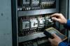
3.3 Electrical Connection Inspection
- Tighten all power terminals, signal connectors, and ground terminals to the specified torque
- Check for loose, oxidized, overheated, or discolored contacts
- Verify the ground connection is reliable (ground resistance ≤4Ω)
- Repair or replace damaged connectors and cables immediately
3.4 Parameter Backup & Calibration
- Back up all configuration parameters, control maps, and fault records using official software
- Calibrate temperature, pressure, speed, and voltage sensors to ensure accuracy
- Verify alarm thresholds and protection logic (overtemperature, overvoltage, overload, low oil pressure)
- Record all calibration data for future traceability
4. Common Faults & Professional Repair Methods
4.1 Power Supply Failure
Symptoms: No display, no indicator lights, module cannot start
Causes: Blown fuse, damaged power circuit, faulty voltage regulator, loose power cable
Repair Steps:
- Check input voltage (match rated voltage of the module)
- Replace blown fuses with the same specification (do not use higher-rated fuses)
- Inspect the power board for burnt components or damaged traces
- Repair or replace the power supply circuit and retest
4.2 Communication Failure
Symptoms: Cannot connect to PC/PLC, lost data, intermittent communication
Causes: Damaged communication port, faulty cable, incorrect baud rate, ground loop interference
Repair Steps:
- Replace communication cable and test on another port
- Check communication parameters (address, baud rate, parity)
- Eliminate electromagnetic interference and improve grounding
- Replace damaged communication chip or control board
4.3 Sensor & Signal Abnormality
Symptoms: Incorrect parameter reading, false alarms, engine unstable operation
Causes: Sensor failure, short/open circuit, signal interference, calibration drift
Repair Steps:
- Test sensor output with multimeter/oscilloscope
- Check wiring for short circuit or poor contact
- Recalibrate sensors or replace faulty ones
- Add shielding to signal lines to reduce interference
4.4 Overheating & Automatic Shutdown
Symptoms: High-temperature alarm, module self-protection shutdown, performance degradation
Causes: Clogged vents, fan failure, high ambient temperature, internal component aging
Repair Steps:
- Clean cooling system and remove dust blockage
- Replace faulty cooling fans
- Improve ventilation or install air conditioning in the control room
- Replace overheated components such as capacitors and regulators
4.5 Firmware & Software Faults
Symptoms: Program crash, wrong parameters, fault codes cannot be cleared
Causes: Firmware corruption, incorrect configuration, virus interference, power failure during update
Repair Steps:
- Restore factory parameters and reconfigure
- Update or re-flash official firmware
- Clear fault codes and perform a full system test
- Avoid sudden power loss during firmware update
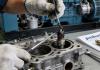
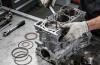
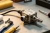
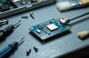
5. Advanced Repair & Component-Level Service
For severe damage, component-level repair is required, which should be performed by certified technicians:
- Circuit board maintenance: repair damaged PCB traces, replace burnt chips, resistors, capacitors, and inductors
- Capacitor replacement: replace electrolytic capacitors with swelling, leakage, or reduced capacity (common aging component)
- Port repair: repair damaged USB, RS485, CAN, or analog ports
- Component testing: use multimeters, oscilloscopes, and program burners to detect and repair core components
- Potting treatment: reapply thermal conductive potting glue for waterproof, dustproof, and shockproof performance after repair
6. Post-Repair Testing & Commissioning
After maintenance or repair, complete the following tests to ensure safe and stable operation:
- Power-On Test: Check voltage, indicator status, and self-test results
- No-Load Test: Verify module initialization, sensor reading, and communication function
- Load Test: Run the engine under low load and gradually increase to rated load
- Protection Test: Simulate fault conditions to confirm alarm and shutdown functions
- Long-Term Stability Test: Continuous operation for 4–8 hours to check for overheating or abnormalities
- Final Confirmation: Record parameters, clear temporary faults, and issue a repair report
7. Spare Parts & Replacement Guidelines
- Use original MWM spare parts or authorized equivalent components to ensure compatibility
- Replace capacitors, fans, and connectors every 3–5 years as preventive maintenance
- When replacing the entire control module, import parameters from backup before power-on
- Store spare modules in dry, anti-static, and vibration-free packaging
8. Best Practices for Long Service Life
- Install the module in a clean, dry, ventilated environment away from heat sources and vibration
- Implement strict daily inspection and record all faults and maintenance history
- Train operators to recognize early warning signs (abnormal lights, slow response, false alarms)
- Update firmware regularly to fix bugs and improve performance
- Avoid frequent power on/off; maintain stable power supply
- Use surge protectors and voltage stabilizers to prevent electrical damage
9. Troubleshooting Summary Table
| Fault Phenomenon | Possible Cause | Solution |
|---|---|---|
| No power | Power failure / Blown fuse / Loose cable | Check power / Replace fuse / Reconnect cables |
| No communication | Wrong settings / Damaged port / Interference | Check parameters / Replace port / Add shielding |
| Wrong sensor data | Sensor fault / Wiring error / Calibration drift | Replace sensor / Repair wiring / Recalibrate |
| Overheating alarm | Dust blockage / Fan failure / High ambient temp | Clean vents / Replace fan / Improve cooling |
| False fault codes | Software error / Parameter loss / Interference | Reset system / Restore parameters / Optimize ground |
| Engine unstable | Control signal error / Output module fault | Check output / Repair driver board |